Flymo 1200R Robotic Mower Teardown
Introduction
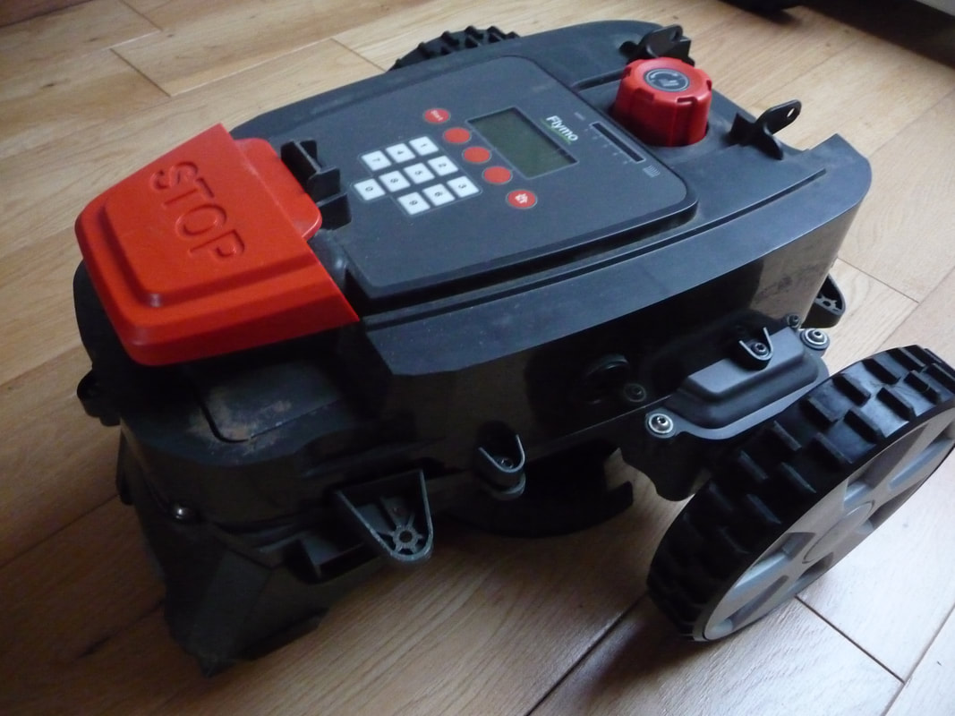
This is not intended to be an extensive teardown or design analysis, merely an overview of the design to satisf my curiosity and with a view to adapting the parts for my own mower project. The robotic mower seems to be Husqvarna Automower 305 manufactured with slight variations and rebadged as the Flymo 1200R, Gardena R40Li and possibly a McCulloch variation
It should be noted that the 1200R that I dismanlted was a genuine customer return as Flymo did provide an unlock PIN after I had provided the mower code and proof of purchase. The mower did unlock but had a persistent fault as well as the charging station did not seem to work. This was not a problem as the original intention was to use the motors for my own project.
Overview
The mower seems to be designed to operate in a random mowing pattern, changing direction when encountering the permitter wire or an obstacle. The permitter wire arrangement is slightly different to other mowers in that in addition to the permitter loop, there is a guide wire which the mower uses to get back to the charging station. The charging station also seems to have its own loop which the mower uses to detect so that it can turn around and reverse into the docking station.
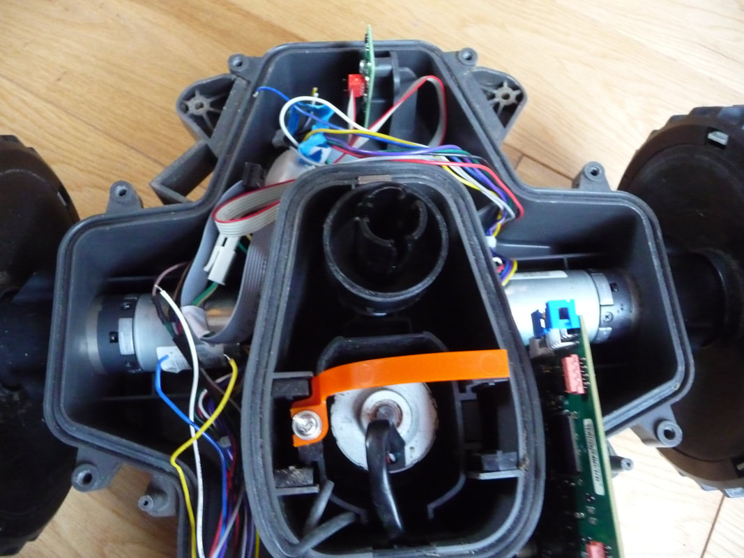
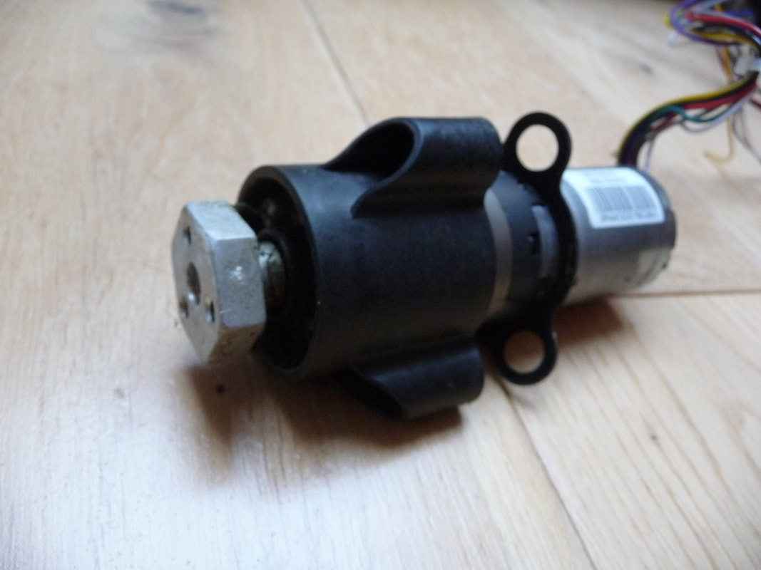
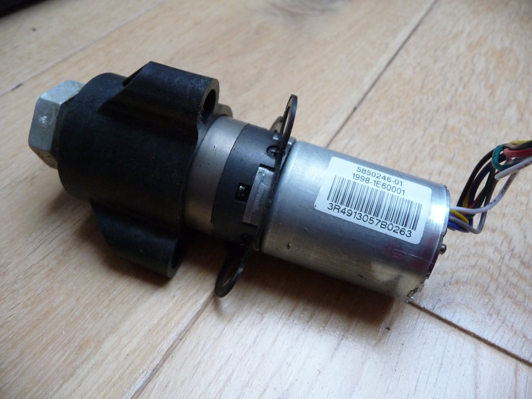
Two brushless DC motors with gearboxes are used to drive two from wheels. There is a ball shaped free wheel at the back which runs on a spindle but the wheel does not pivot when turning left or right and is effectively dragged across the lawn when not going in a straight line. This probably helps it keep in a relativley straight line when operating one uneven and wet ground. A flap on the top covers a keypad and LCD display. When ever
A third brushless DC motor directly drives the cutter disc which has 3 thin double edged blades which permits the motor to be in either direction and get more use out of the blades.
The mower appears mechanically to be well designed with attention to protection from water ingress using seals and a clear conformal coating on all PCB assemblies.
spend as 20W while mowing?
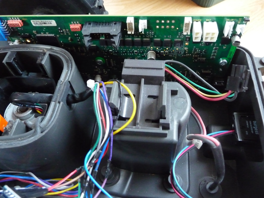
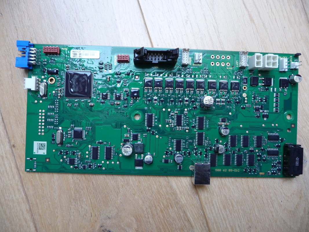
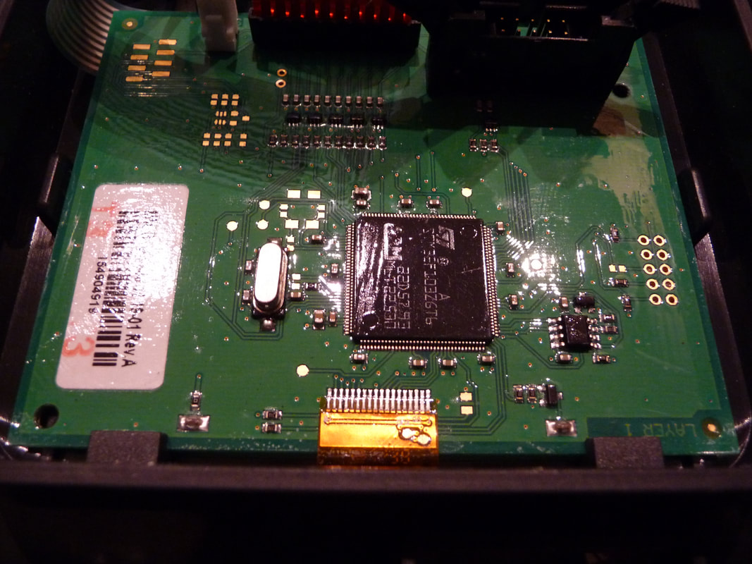
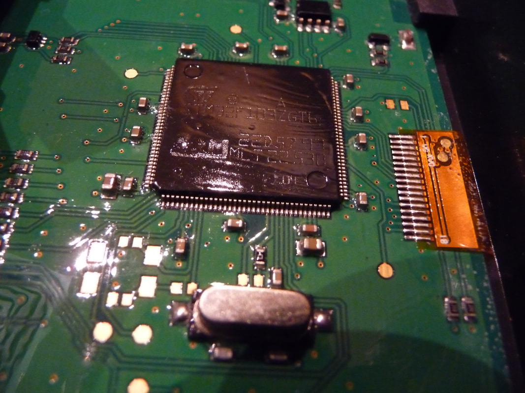
The internal PCBs have a clear control coating to protect from moisture
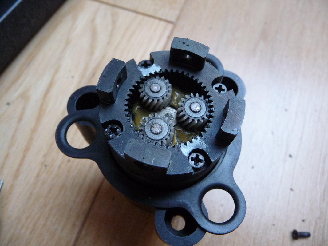
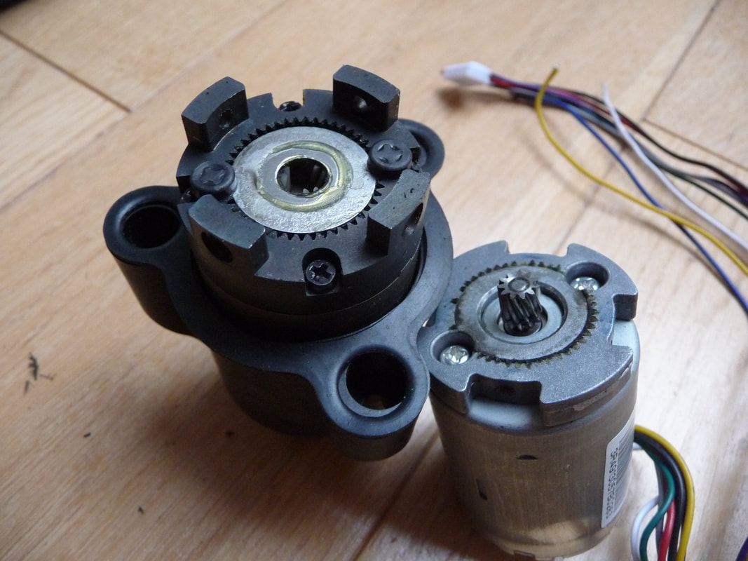
2 x Geared wheel motors with Hall Effect position sensors approx (100:1) BLDC, 3 phase
1 x Cutter motor (with 3 small bi-directional cutting blades)
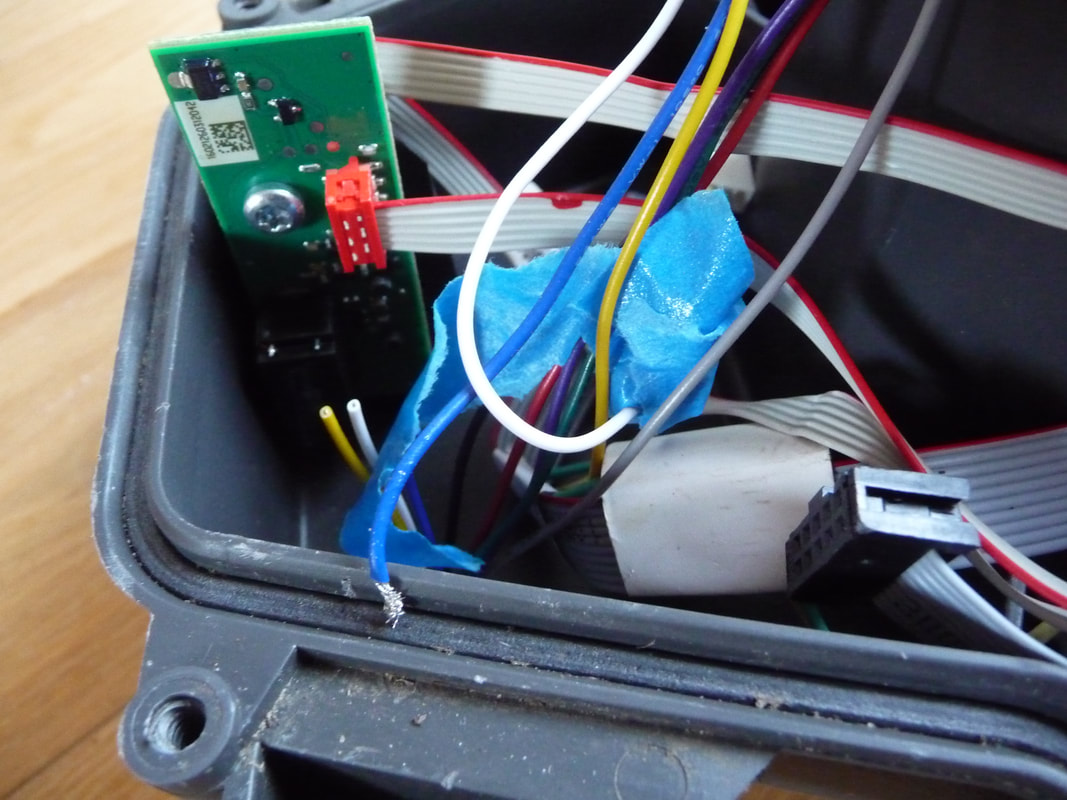
2 x Perimeter wire sensor coils (1 at the front and 1 at the rear)
2 x Hall Effect sensor (1 at the front and 1 at the rear)
1 x 3 Axis accelerometer (located on main PCB)
1 x Emergency stop microswitch (on top cover)
1 x Main On/Off switch (at rear)
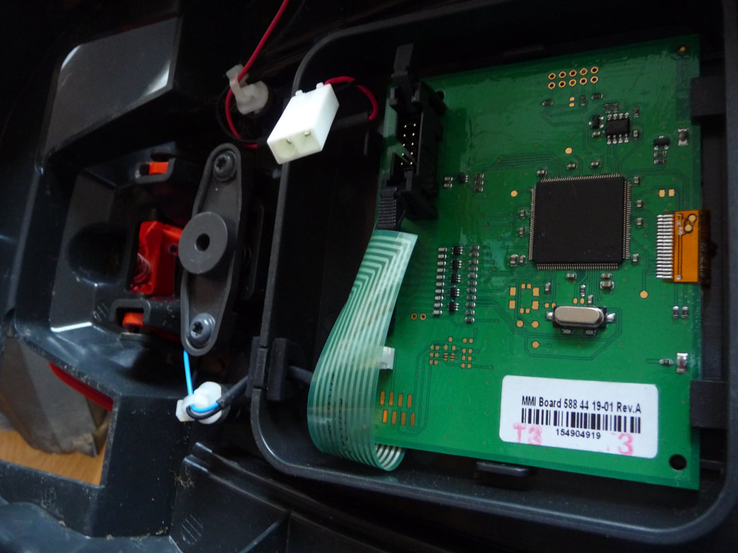
1 x Keypad and LCD display
1 x Piezo sounder (in top cover)
1 x Battery LiPo Pack, 18.5V 2.1 Ah (5 x 18650 cells in series with integrated charge and monitor PCB)
The Horseshoe Crab'esque cover shell is fastened to the chassis using 4 rubber mounts which support the weight of the shell but easily allow longitudinal and lateral movement. This movement, combined with two Hall Effect switches in the main body (one front and rear), allows the mower to detect collisions with obstacles. A slot at the front in the top part of the body, and a corresponding protrusion in the top shell, constrains the top shell movement to forward or rearward thus being able to detect obstacles in front to behind, depending on direction of motion. The rear of the top shell is not constrained and thus can detect side movements as well. This is presumably to detect obstacles when turning.
helical gear on the motor to help minimise noise
This is not intended to be an extensive teardown or design analysis, merely an overview of the design to satisf my curiosity and with a view to adapting the parts for my own mower project. The robotic mower seems to be Husqvarna Automower 305 manufactured with slight variations and rebadged as the Flymo 1200R, Gardena R40Li and possibly a McCulloch variation
It should be noted that the 1200R that I dismanlted was a genuine customer return as Flymo did provide an unlock PIN after I had provided the mower code and proof of purchase. The mower did unlock but had a persistent fault as well as the charging station did not seem to work. This was not a problem as the original intention was to use the motors for my own project.
Overview
The mower seems to be designed to operate in a random mowing pattern, changing direction when encountering the permitter wire or an obstacle. The permitter wire arrangement is slightly different to other mowers in that in addition to the permitter loop, there is a guide wire which the mower uses to get back to the charging station. The charging station also seems to have its own loop which the mower uses to detect so that it can turn around and reverse into the docking station.
Two brushless DC motors with gearboxes are used to drive two from wheels. There is a ball shaped free wheel at the back which runs on a spindle but the wheel does not pivot when turning left or right and is effectively dragged across the lawn when not going in a straight line. This probably helps it keep in a relativley straight line when operating one uneven and wet ground. A flap on the top covers a keypad and LCD display. When ever
A third brushless DC motor directly drives the cutter disc which has 3 thin double edged blades which permits the motor to be in either direction and get more use out of the blades.
The mower appears mechanically to be well designed with attention to protection from water ingress using seals and a clear conformal coating on all PCB assemblies.
spend as 20W while mowing?
The internal PCBs have a clear control coating to protect from moisture
2 x Geared wheel motors with Hall Effect position sensors approx (100:1) BLDC, 3 phase
1 x Cutter motor (with 3 small bi-directional cutting blades)
2 x Perimeter wire sensor coils (1 at the front and 1 at the rear)
2 x Hall Effect sensor (1 at the front and 1 at the rear)
1 x 3 Axis accelerometer (located on main PCB)
1 x Emergency stop microswitch (on top cover)
1 x Main On/Off switch (at rear)
1 x Keypad and LCD display
1 x Piezo sounder (in top cover)
1 x Battery LiPo Pack, 18.5V 2.1 Ah (5 x 18650 cells in series with integrated charge and monitor PCB)
The Horseshoe Crab'esque cover shell is fastened to the chassis using 4 rubber mounts which support the weight of the shell but easily allow longitudinal and lateral movement. This movement, combined with two Hall Effect switches in the main body (one front and rear), allows the mower to detect collisions with obstacles. A slot at the front in the top part of the body, and a corresponding protrusion in the top shell, constrains the top shell movement to forward or rearward thus being able to detect obstacles in front to behind, depending on direction of motion. The rear of the top shell is not constrained and thus can detect side movements as well. This is presumably to detect obstacles when turning.
helical gear on the motor to help minimise noise