RGB Light Bulb
|
There are a number of RGB Light bulbs with an IR remote control on the market with a widely varying price range. They are not really much good as replacement light bulbs but could be useful if you wanted to add some controlled LED lighting to something. If you look around the Internet you can find some relatively cheap ones but amazingly I found that CPC / Farnell was selling some E27 style light bulbs with a remote for £4.86. This is a lot less than most eBay sellers and even some Chinese suppliers, so I grabbed one to see if I could re-purpose it to add some decorative lighting to a glass ornament at home. The following is a brief teardown of the lightbulb and how I re-used it.
|
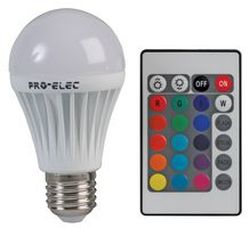
The victim - 3W RGB colour changing bulb with remote
|
The teardown
The dome is attached using a white silicone rubber glue/sealant which can be prised off by carefully using a craft knife blade or just by chipping away at the holder using some flat pliers then prising the dome off. Since I did not want to use the holder again I went for the later safer method.
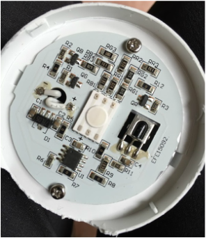
Main PCB ModuleThe IR receiver has a square metal can around the back and sides. This might be to screen any IR from the body behind. The PCB and heat spreader have square cut outs behind it as well.
|
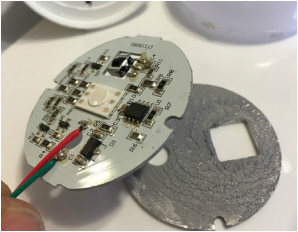
PCB & HeatsinkThe aluminium heatsink has a good smear of a thermal paste to help conduct the heat away from the main PCB, which also appears to have an aluminium substrate.
|
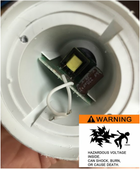
Power SupplyCaution this is a non-isolated design so there will be live mains and high DC voltages on parts of this PCB so best to throw this bit away.
|
Under the dome there is a small single sided PCB attached to the base using two small self tapping screws. There are two wires that connect to a small power supply module fitted into the base. The circuit is relatively simple and the main parts of the circuit appear to be as follows: -
The power supply module sits underneath the main PCB and produces approximately 19V DC. However, it seems to be a non-isolated step-down design so don't mess with this as there will be live mains and a high DC voltage on the PCB. In this case the UK mains voltage is 230V AC so the rectifier stage will have around 540V DC. It was pleasing to not the that there appeared to be a thermal fuse on the AC input, which is nice to se in something for less than £5 (still can't believe that is the correct price) but I would still throw it away and use an isolated DC supply if you intend to use it for anything else.
Note that some really cheap designs use a 5V DC supply which saves on having the 5V DC voltage regulator but makes them less flexible for reducing the LED current by reducing the supply voltage. Also, a very cheap Chinese version (????) that I had looked at earlier had a third wire which was used to supply a 50Hz mains clock to drive the IC on the main PCB. Interesting the remote looked identical to the PRO-ELEC part but operated completely different to it.
The SOT23 surface mount transistors are marked VS30 but I could not find any data on these and assume them to be N channel FETs capable of at least 1 amp current capability, possibly with a 30V max rating.
Several 0 ohm chip resistors are used as wire links to enable a single sided PCB construction to be used.
Three series chip resistors are fitted to each of the three LED drive stages to set the current for each colour. In this case the total series resistance for the R, G and B LEDs is 294, 120 and 312 ohms respectively.
Lamp power is stated as 3 watts which does not sound much but when it is concentrated into the small area of the RGB LED it can get quite hot. In this product, the heat is managed using an aluminium PCB substrate with an aluminium heatsink / heat spreader placed directly below it with some thermal paste sandwiched between the two. The thermal resistance between the PCB and heatsink assembly and the lamp body must be quite high but I didn't run it for long to see how warm the body got before I dismantled it.
- 5V (78L05) voltage regulator
- RGB Control IC (8 pin SOIC)
- RGB LED wired as common anode (Centre)
- IR Receiver IC (with partial metal screen)
- Three separate LED drive FET stages (10k gate drive resistor, SOT23 FET and series load limiting chip resistors)
The power supply module sits underneath the main PCB and produces approximately 19V DC. However, it seems to be a non-isolated step-down design so don't mess with this as there will be live mains and a high DC voltage on the PCB. In this case the UK mains voltage is 230V AC so the rectifier stage will have around 540V DC. It was pleasing to not the that there appeared to be a thermal fuse on the AC input, which is nice to se in something for less than £5 (still can't believe that is the correct price) but I would still throw it away and use an isolated DC supply if you intend to use it for anything else.
Note that some really cheap designs use a 5V DC supply which saves on having the 5V DC voltage regulator but makes them less flexible for reducing the LED current by reducing the supply voltage. Also, a very cheap Chinese version (????) that I had looked at earlier had a third wire which was used to supply a 50Hz mains clock to drive the IC on the main PCB. Interesting the remote looked identical to the PRO-ELEC part but operated completely different to it.
The SOT23 surface mount transistors are marked VS30 but I could not find any data on these and assume them to be N channel FETs capable of at least 1 amp current capability, possibly with a 30V max rating.
Several 0 ohm chip resistors are used as wire links to enable a single sided PCB construction to be used.
Three series chip resistors are fitted to each of the three LED drive stages to set the current for each colour. In this case the total series resistance for the R, G and B LEDs is 294, 120 and 312 ohms respectively.
Lamp power is stated as 3 watts which does not sound much but when it is concentrated into the small area of the RGB LED it can get quite hot. In this product, the heat is managed using an aluminium PCB substrate with an aluminium heatsink / heat spreader placed directly below it with some thermal paste sandwiched between the two. The thermal resistance between the PCB and heatsink assembly and the lamp body must be quite high but I didn't run it for long to see how warm the body got before I dismantled it.
The Hack
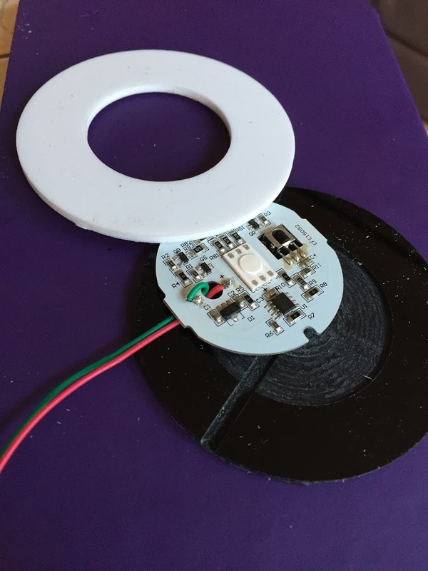
The PCB is easily removed by disconnecting the two wires that go to the power supply using a soldering iron. The PCB is approximately 47mm diameter and, without the heatsink, the maximum board height is about 4mm making it ideal for lighting the glass ornamnet that I had in mind. However, I did not want to have to dissipate power/heat into the ornament but since the control IC is powered from a linear regulator, it is possible to run the module at a lower voltage to reduce the dissipation.
With the main PCB connected to a 12V DC supply, the current consumption is approximately 32mA (White full on) and the light output is easily bright enough for my application. As the power dissipation is in the order of 70% lower, the the RGB LED barely gets warm. In standby mode (all LEDs off) the current combustion was approximately 4.1mA.
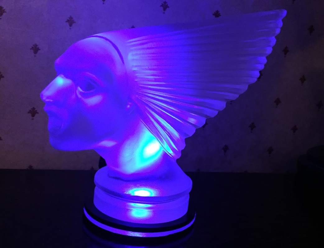
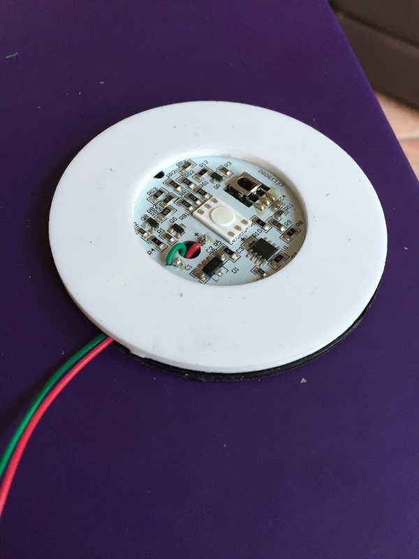
Placing a transparent or translucent object or anything that acts as a light guide over the LED module illuminates it quite nicely. The object also acts as a light guide the in the other direction which allows the IR remote to work quite well to control the RGB module.
There is a crude power/brightness control operated by the remote with five selectable levels which varies drive to each RGB LED from full On to about 50:50 PWM (This is a guess as I wasn't able to measure it).
The good
The main PCB is slim to use as low profile lighting such as kitchen cabinets or even RGB beer mats. Picks up the IR remote quite well. If you can get a cheap one you can illuminate you beer glass etc.
The bad
its not very good. Not much in the way of brightness control. The strobe and flash functions are awful.
With the main PCB connected to a 12V DC supply, the current consumption is approximately 32mA (White full on) and the light output is easily bright enough for my application. As the power dissipation is in the order of 70% lower, the the RGB LED barely gets warm. In standby mode (all LEDs off) the current combustion was approximately 4.1mA.
Placing a transparent or translucent object or anything that acts as a light guide over the LED module illuminates it quite nicely. The object also acts as a light guide the in the other direction which allows the IR remote to work quite well to control the RGB module.
There is a crude power/brightness control operated by the remote with five selectable levels which varies drive to each RGB LED from full On to about 50:50 PWM (This is a guess as I wasn't able to measure it).
The good
The main PCB is slim to use as low profile lighting such as kitchen cabinets or even RGB beer mats. Picks up the IR remote quite well. If you can get a cheap one you can illuminate you beer glass etc.
The bad
its not very good. Not much in the way of brightness control. The strobe and flash functions are awful.
|
|
|
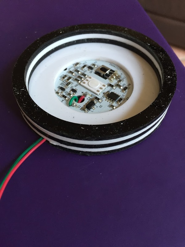
The base was built up using sheets of acrylic which can be cut to any shape you like using if you can get access to a CNC machine of Laser cutter.
